shawn tu soude ton jtag a coter des 12 trou pour le jtag ya une place drette a coter ya 6 ti carrer tourne ton board de bord pi ta 6 autre ti carrer tu soude ton jtag la jva essayer de de fair eune foto de mon routeur ou bin en trouve rune belle foto pour te montrer exactement c ou _________________ Linksys WRT610N V1 (CFE .16)
Asus WL-500W
D-Link DIR-825
Posted: Mon Nov 24, 2008 18:07 Post subject: any other advice?
I've got a bricked WRT310N, but I cannot get past the message the original poster showed in his first post.
I've made sure my jtag header is in the right spot (thanks to all the good pictures, and I've made sure my connections are good for pins 3, 5, 7 9 and 6 (on the reverse). Since these are the only pins connected on the cable I bought, I think this should work.
Whenever I try "tjtagv2 -probeonly" or "tjtagv2 -probeonly /noemw" I get the same "*** Unknown or NO CPU Chip ID Detected ***" message.
Any additional advice, or is this thing irrecoverable? The power light does come on when I plug it in, but it flashes blue.
Posted: Mon Nov 24, 2008 19:42 Post subject: thanks Piketeam
Thanks for your reply. Soldering everything didn't make much sense to me since only the pins I've listed are connected to anything on the other end of the ribbon cable. What the heck... I'll try it anyway.
As you can see from the post above I've tried "tjtagv2 -probeonly /noemw" with no luck. I also tried "tjtagv2 -probeonly /nodma" in case DMA access was the issue...
I got a serial console rs232 (3.3v) port working on the Linksys WRT310N Broadcom router.
It has a serial port on the motherboard that is exposed via the WAN Ethernet port. I've heard of this on newer Linksys routers. There are contact pads you can see inside the WAN port on the bottom. Linksys has some special cable for diagnostics to get in this way. If you look close, you can actually see TX RX and GND printed on the circuit board.
Continuity tester reveals the pad on the underside of the board is a duplication of the labeled serial port underside of WAN Ethernet jack.
This is the 5 gold pads on the UNDERSIDE of the board, near the (bottom) Broadcom bcm4705 chip. the pad says "B2" in very tiny print.
pin 2 - TX
pin 3 - RX
pin 5 - GND
Works like a charm. I soldered solid Ethernet wire to the surface pads then hot glued them to hold them in place.
I am having an issue and I'm hoping someone can help.
I have a Linksys WRT310N and I bricked it (I D 10 T)
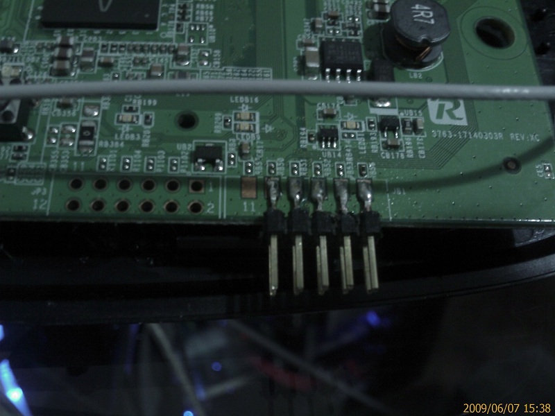
I attached a header to the PCB like this:
I left the 11 and 12 pins off since they don't physically attach to anything in the cable.
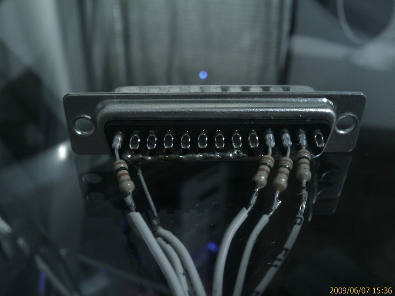
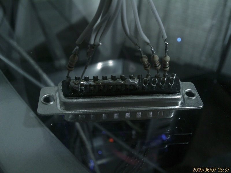
Then I made the cable like this:
Note-
18-25 to 2,4,6,8,10
13 to 5
4 to 7
3 to 9
2 to 3
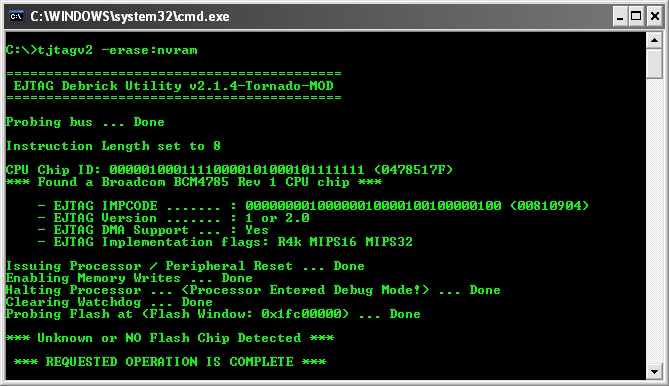
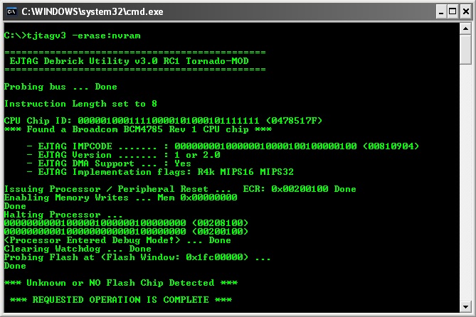
The cable seems to be working but I am receiving an error when running the jtag utility. As you can see from the following images,
the CPU is recognized,
Reset is successful,
Enable Writes is successful,
CPU enters Debug,
and Watchdog clears.
My issue is the flash memory is not recognized.
This is a screenshot from V2.1.4
And this is a screenshot from V3rc1
Any help would be greatly appreciated. I am so close I can feel it.
Last edited by fearreality on Sun Jun 07, 2009 22:12; edited 1 time in total